
Pseudo - steady - state equation Oil and gas reservoirsDarcy equationParameters used in equation :PermeabilityThicknessRadius (reservoir external drainage) / Area / ShapeSkin (dimensionless skin factor)Wellbore diameterGas well: laminar and turbulent flow Oil well: laminar flow Schellhardt & Rawlins empirical equationNormally, 0.5 < n < 1.0 Jones equationGas and saturated oil reservoirs Equations:Gas:(P2) = AQ + BQ2 Oil:(P) = AQ + BQ2whereA : Laminar flow coefficient (Darcy)B : Turbulent flow coefficient (Non Darcy)Also known as Forcheimer equationīack pressure equationFor gas wellsQ = C (Pws2 - Pwf2)n The lower the value of n, the greater the degree of turbulence Qmax = Absolute Open Hole PotentialPws = Static Reservoir Pressureįetkovichs equationAlternative to Vogels equationEmpirical correlationq / qmax = n Where, C = PI Coefficient, normal value is 0.8 Vogels equationEmpirical relationship for fluid below bubble point pressure: Where,Pws = static reservoir pressurePwf = flowing bottom-hole pressureQ = flowrate

Well productivity index (PI)For LiquidQ = PI x (Pws - Pwf)įor gas compressible reservoirs Q = PI x (Pws2 - Pwf2) Well Productivity Index Back Pressure EquationJones EquationPseudo-Steady-State EquationHydraulic FractureForcheimer Transient Well Productivity Index Vogel Equation Fetkovich Equation Jones EquationPseudo-Steady-State EquationHydraulic Fracture Transient Inflow performance relationshipsOil Reservoirs: Well completion modelsWell PI (Oil & Gas)Vogel Equation (Oil)Jones (Oil & Gas)Fetkovich Equation (Oil)Back Pressure Equation (Gas)Pseudo Steady State (Oil & Gas)Forcheimers Equation (Gas & Condensate)Hydraulic Fracture (Oil & Gas)Transient (Oil & Gas) Single branch toolboxPOINTERCONNECTORMULTIPLIER/ ADDERNODEHORIZONTAL COMPLETIONTUBINGVERTICAL COMPLETIONREPORT TOOLNA POINTCOMPRESSOREXPANDERPUMPSEPARATORHEATER/ COOLERCHOKERISERFLOWLINESOURCEKEYWORD INSERTERINJECTED GASANNOTATIONBOUNDARY NODEMULTIPHASE BOOSTER tubing ID, etc.Enter fluid data: black oil/compositionalSet boundary conditionsSelect an operation well completion, tubing, etc using the toolbo圎nter physical data, i.e. Solution algorithmSolution computed in flow directionEach pipeline is divided into a number of segments determined automaticallyPressure and energy balances in each segmentFluid physical properties are calculated at averaged conditions across each segmentFlow regime determined from gas and liquid superficial velocitiesīuilding a modelDefine objects in the model, i.e.

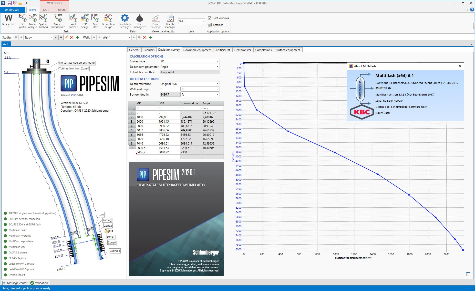
It has three fundamental iteration options (with inlet temperature always defined):Non-Iterative Pin and Qin known, calculate PoutIterate on Pressure Qin and Pout known, calculate PinIterate on Flowrate Pin and Pout known, calculate Qin PIPESIM performs simultaneous pressure and temperature calculations. Iteration Options:PIPESIM is a steady state multiphase flow simulator. PIPESIM Basics: PIPESIM File Naming and structureSingle Branch Model Basics (Iteration Options).Building a Model.Description of PIPESIM Model Components.Single Branch Operations.įile namingGUI input filesxxx.bpsPIPESIM input file (single branch)xxx.bpnPIPESIM input file (network)xxx.pgwinput filexxx.pvtFluid Property PIPESIM-GOAL input filexxx.fptFPT input fileOutput filexxx.out Output filexxx.sumSummary tJob plot (1 data point for each case)xxx.plcCase plot (1 data point for each node)


 0 kommentar(er)
